FPGA Reaction Time Meter
University project: Reaction time meter on the Digilent Nexys 4 DDR FPGA board, implemented in VHDL.
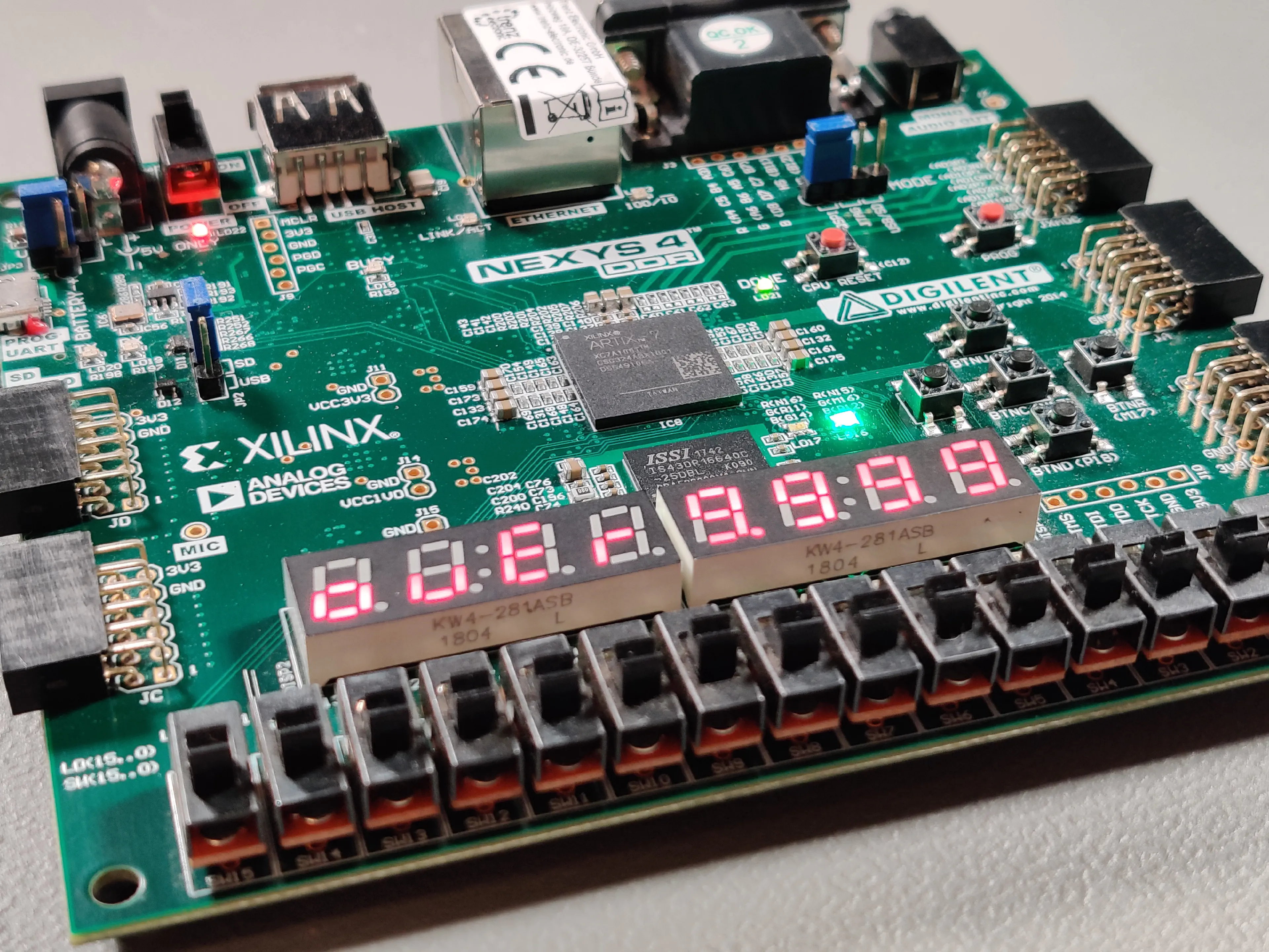
For my digital-systems-development lecture I had to implement a reaction time meter in VHDL on a FPGA. I was provided with a list of functional requirements and a development board (Digilent Nexys 4 DDR). The board is based on the Xilinx Artix-7 XC7A100T-1CSG324C, which is more than capable for this project. Additionaly, a lot of in- and outputs are available: Buttons, Switches, LEDs, 7-segment displays, …
In the picture you can see the board configured with my gateware. After the press off a button, a random timer is activated to make the start of time counting less predictable. The current time is shown on the display. When it is not stoped by a button again, it times out after 9999 ms with an “over” notice.

For me, this is the first time using a FPGA. I’ve wanted to learn a hardware description language for a long time, but never found the time. So I took this project as an oportunity to familiarize myself with VHDL and the basics of FPGA development.
This are the key functions/features:
- A state machine controlled by a debounced button
- Starting the time counter after a random delay
- Stopping the counter on overflow and button press
- Displaying the time on a multiplexed 7-segment display
- Showing an overflow notice on the display
- Signaling the ready-state with a LED
- Simulating every module with testbenches
I got everything running as required; Unfortunately my gateware never got checked by an expert. I taught VHDL myself by browsing StackOverflow and watching YouTube videos, all while being under time pressure. At this point, I’m still quite inexperienced and my code for sure contains a lot of flaws. I would be grateful to get some feedback to extend my knowledge on this topic.
In the future I want to work on some more FPGA-projects. I will probably switch to Verilog, though, because it seems to be more popular than VHDL.